
The exhaust pipe holds more information about your engine than almost any other place on the car. Every combustion event leaves a chemical signature behind, and the amount of unused oxygen in that exhaust stream tells you how closely the fuel delivery matched what the engine needed. Capturing that signature accurately is the job of a Haltech wideband oxygen sensor controller.This handbook takes a hands on approach. Instead of simply describing what the device is, it walks through selecting parts, preparing the exhaust, building the wiring, calibrating the sensor and solving the most common installation problems. If you intend to fit a system yourself, treat it as a working checklist.
How Exhaust Oxygen Measurement Works
Exhaust oxygen measurement is based on a simple principle: burn a fuel with exactly the right amount of air and virtually no oxygen is left. Burn it with excess air and oxygen remains. Burn it with excess fuel and there is a surplus of unburnt hydrocarbons and carbon monoxide that consume what little oxygen is available.
A wideband oxygen sensor quantifies that balance across a very large range. Rather than reporting only rich or lean, it reports how rich or how lean. The controller supplies the sensor with a precise heater drive, measures the pump current needed to keep the internal reference cell balanced, and converts the result into lambda. The sensor is the measuring probe, while the controller is the brain that makes the reading meaningful.Because the result is only as good as the exhaust sample, the sensor must be placed where the gas is representative, sealed against air leaks and kept at the correct temperature. Those three conditions explain most of the advice in the rest of this guide.
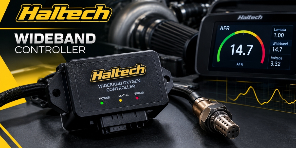
What the Haltech O2 Sensor Controller Contains
A Haltech O2 sensor controller is a compact electronic module with several functional blocks. A heater driver regulates sensor temperature, a precision measurement circuit reads pump current, a microcontroller performs the calculations and a communication stage sends the answer out. Depending on the model, that communication stage may include CAN output, analogue output or both.
The module is sealed against moisture but is not designed to sit in extreme heat. Mount it in a cabin or a protected engine bay location where the temperature stays moderate. Keep it away from turbochargers, exhaust manifolds and brake ducting.Some models are single channel, so they drive one sensor. Dual channel versions drive two sensors from one housing, which suits V engines and twinturbo installations where each bank needs its own reading. Always check the specification of your exact unit before you plan the harness.
Choosing the Sensor Why Bosch LSU 4.9 Matters
Most modern aftermarket wideband controllers are built around the Bosch LSU 4.9, a planar sensor with a long record in production vehicles and motorsport. It is widely available, reasonably priced and extremely well documented, which makes both installation and diagnosis easier.
The key point is that the controller and sensor are a matched pair. The controller expects the electrical characteristics of a specific sensor type, and its calibration is based on them. Substituting a different sensor, even one that physically fits, can lead to reading errors. Likewise, replacing a sensor with a counterfeit or low quality copy can cause drift, slow response or early failure. Buy sensors from reputable sources and replace them with the same type.Fuel compatibility is the other consideration. Standard Bosch wideband sensors are made for unleaded fuels. Leaded racing fuel and certain additives can shorten sensor life dramatically, because lead deposits poison the sensing element. If you run a leaded fuel, check the sensor manufacturer's guidance and expect a shorter service life.
Preparing the Exhaust and Fitting the Sensor
Good installation starts with the exhaust. Plan the location before you cut anything.
Select the position. On a turbocharged car, fit the sensor downstream of the turbine, far enough back for gas to mix but ahead of the catalytic converter if there is one. On a naturally aspirated engine, use the collector or the first section after it. In both cases, avoid positions right next to the exhaust port, where gas temperatures are highest and the sensor is most likely to overheat.
Choose the angle. Install the bung so the sensor sits in the upper half of the pipe, ideally tilted between 10 and 90 degrees above horizontal. This keeps condensate from pooling against the ceramic element, because thermal shock from liquid water on a hot sensor can crack it.
Weld the bung. Use the supplied bung, align it carefully and weld it with a gas shielded process. Let the pipe cool, then clean the thread of weld spatter. A damaged thread can seize or leak.
Fit the sensor. Screw it in by hand first, then tighten to the specified torque. Do not use general purpose thread paste on the sensing end, because silicones and some antiseize compounds can contaminate the element.
Route the cable. Keep the cable away from the exhaust surface and tie it up so it cannot hang in heat or rub against sharp edges. Leave a gentle loop so the cable does not pull on the connector.
During the harness build, consider how many sensors and auxiliary circuits will share the exit point from the engine bay. A sealed circular or rectangular interface such as the ASDD10609PNHE can serve as the dividing point between the engine harness and the cabin harness, keeping dirt and water out of the connection.
Haltech Wideband Controller Wiring Step by Step
Wiring is the stage where careful work pays back immediately. The following sequence reflects common practice for a CANconnected installation.
Plan the cable route. Keep the controller, power feed and CAN cable well away from ignition coils, ignition leads and alternator output cables.
Run the power feed. Use appropriately rated wire and a fuse close to the source. The heater draws considerable current while the sensor warms up, so a thin or poorly crimped wire will cause voltage drop.
Establish the ground. Terminate the ground at a clean, bare metal point or a dedicated engine management ground. Avoid sharing it with starter motors or fans.
Connect the CAN pair. Use twisted pair cable, keep stubs short and verify termination resistors at each end of the bus. A properly terminated bus measures roughly 60 ohms between CAN high and CAN low with the system powered down.
Connect the sensor. Plug in the sensor connector only after confirming power and ground. Never leave a powered controller with a disconnected sensor in a hot exhaust.
Optional outputs. If you use an analogue output for a gauge, use shielded cable and ground the shield at one end only.
Take time over crimps and seals. Use proper crimp tools, support the cable at regular intervals and use heat shrink with adhesive lining for splices. Many intermittent wideband faults are really connector faults. When the project includes several sensors on a single bulkhead, a flangestyle socket such as the ASDD9WAYFLGSKTNKEYRED is a tidy and robust option.
Understanding a Wideband O2 Sensor Wiring Diagram
When you read a wideband O2 sensor wiring diagram from any manufacturer, it helps to know what each group of wires does. The sensor connector normally carries six conductors two for the heater, and four for the sensing and pumping circuits, which include the pump current line, the reference cell and a calibration resistor or trimming signal. You do not need to modify these wires, and you should not splice into them.
On the controller side, the harness separates those functions into a sensor connector, a power and ground feed and an output group. The output group is where your choice between CAN and analogue is made. Colour codes differ between product generations, so rely on the diagram supplied with your exact unit rather than on memory or an online image from a different model.
A diagram is only half the job. After building the harness, check continuity, polarity and insulation before applying power. A multimeter and a few minutes of checking can prevent a damaged controller.
Haltech ECU Integration and Software Configuration
Once the hardware is installed, the controller needs to be introduced to the ECU. In Haltech NSP you add the wideband controller as a CAN device. You select the correct device type, set the CAN identifier to match the unit and confirm that the bus speed agrees on both sides.
Next, map the incoming lambda value to the ECU's lambda input. If you have two sensors, map one to each bank. Then set the fuel type and target tables. With these steps complete, the lambda reading should appear live in the software. Check it with the engine off and the sensor in clean air, and then start the engine and watch the value settle to a believable number.If you want the ECU to correct fueling automatically, enable closed loop control only after the base tune is sound. A closed loop is a refinement tool, not a substitute for a correct map. Limit the correction authority, set a minimum engine temperature, and disable correction during extreme conditions such as deceleration fuel cut, where the exhaust contains almost pure air.
Calibration, FreeAir Check and Validation
A proper Haltech sensor calibration procedure is the final reassurance that your readings are trustworthy. With a new sensor, perform the free air calibration described in the manual. The idea is to expose the sensor to ambient air, which has a known oxygen concentration of about 20.9 percent, and let the controller record that reference.
To do this properly, make sure the sensor is clean, dry and in open air rather than in a pipe filled with exhaust residue. Allow it to warm up for the time specified, run the calibration routine and confirm that the display returns a value around the expected figure. If the value is far off, check the supply voltage, ground and sensor connector before repeating.
Validation does not stop there. After the first start, check that idle lambda is steady, that it responds quickly to throttle changes and that it moves in the correct direction when you add or remove fuel. A simple test is to adjust the fuel trim by a small percentage and verify that the reading changes by a proportional amount.
Troubleshooting Guide
Use the following quick reference when something does not look right.
No reading at all. Check power, ground, fuse, CAN wiring and address. Confirm the sensor is plugged in.
Reading shows fresh air continuously. The sensor might be out of the exhaust stream, or there is a large exhaust leak.
The heater does not reach temperature. Look for low supply voltage, poor ground or a damaged sensor cable.
Readings are noisy. Reroute the cable away from ignition systems and improve the ground.
Slow response. The sensor may be old, contaminated or too far downstream.
Reading differs from another gauge. Remember that different systems may use different fuel settings and calibration, so compare lambda rather than AFR.
When a fault persists, swap one component at a time. Replace the sensor first, then the connector, then the controller. Changing everything at once leaves you with no idea what actually fixed the problem.
For installations that need a larger number of ways, such as engine bay interfaces that combine sensors, injectors and switches, the ASDD41WAYFLGSKTNKEYRED provides a highcapacity sealed connector that can reduce the number of separate plugs on the car.
Maintaining the System Over Time
A wideband system is not completely maintenance free. Inspect the sensor cable and connector at every service for chafing, heat damage and corrosion. Check the exhaust for leaks, because a new leak ahead of the sensor will change readings immediately. Recheck the free air reading if you replace the sensor or notice drift.
Sensor service life varies with fuel quality, mixture and operating temperature. Harddriven competition engines may need replacement far sooner than a road car. Keep a spare sensor in your toolbox so a failure does not end a test day.Finally, keep a written record of your settings CAN address, bus speed, fuel type and calibration dates. When you return to the car months later, or hand it to a different tuner, that record saves time and avoids mistakes.
Conclusion
A Haltech wideband oxygen sensor controller is only as good as the installation around it. Select the right sensor, mount it in a representative, cool and drained location, build a clean power, ground and CAN harness, and calibrate it before you trust the numbers. Then validate the readings, maintain the system and use the data responsibly.If you are ready to build or upgrade the wiring that supports your sensors, explore the sealed connector range at Arctic Performance Parts and choose parts that match the demands of a motorsport environment.
Frequently Asked Questions (FAQs)
What is a Haltech wideband oxygen sensor controller used for?
It operates a wideband oxygen sensor and converts its signal into an accurate lambda or AFR reading. The result can be displayed, logged and used by a Haltech ECU for closed loop fuel control.
Can I install the sensor before the turbocharger?
It is not recommended. Preturbo temperatures and pressure pulses are very harsh, and sensor life is usually much shorter. Downstream of the turbine is the standard location.
Why does the sensor need free air calibration?
Freeair calibration gives the controller a known oxygen reference, ambient air at about 20.9 percent oxygen, so it can correct for sensor to sensor variation and ageing.
Can I use the controller with E85 or ethanol blends?
Yes, wideband sensors work with ethanol blends. Select the right fuel type in the software so the AFR display is correct, and keep in mind that fuel system hardware must also be ethanol compatible.
How do I know if the sensor has failed?
Typical signs include slow response, readings that will not calibrate, heater error codes, constant fresh air readings or values that disagree with a known good second sensor.